
Embedded Devices: Pwning a Router Part 1 - Attaching to UART
Introduction

Embedded device security research is an adventure like no other. In this multipart blog series, I embark on a journey towards pwning a NETGEAR router. For part 1, I will document my efforts in conducting initial hardware reconnaisance and obtaining a root shell via the debug interface. In later parts, I will focus on reversing and exploiting service binaries.
Target device: AC1200 Nigthawk Smart Wifi Router (R6220)
Hardware Reconnaisance
Gathering information on the hardware of a device begins at identifying the device’s model number or FCC ID. Devices that are sold in the United States and engage in any sort of radio communication/transmission have to be certified by the FCC and are assigned this ID. Most often, it is printed on the back of the device itself. By performing a lookup on the fccid.io website using the FCC ID, we can gather internal photos and other useful information. This will help in identifying hardware components such as the processor chip, flash memory, and any potential debug ports that can be leveraged to obtain a root shell.
From the internal photos, we can leverage the pictures for each chip and identify their model number.
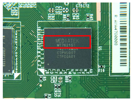
After identifying all the chips and their respective model numbers, we can search for their datasheets. The datasheet will yield useful information we will put to use later. As an example, through the processor’s datasheet we know that its architecture is 32 Bit MIPS and runs Linux 2.6 SDK.
Adding labels to the internal photo picture from the fcc website - we know the following:
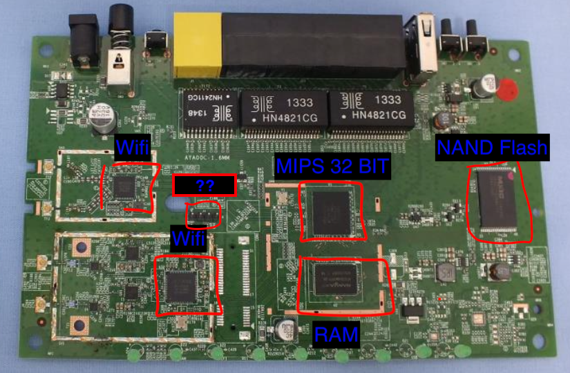
Hunting for Debug Ports
What is most interesting in the figure above are the four aligned header pins labeled with ‘??’. This is a common port alignment for the UART interface. UART allows for asynchronous serial communication in which the data format and transmission speeds are configurable (more on this later). In other words, it is a protocol for communications within an embedded system. UART uses four seperate pins: Power (Vcc), Ground (GRND), RX (Read), and TX (Write).
As shown in the picture below, on my own device there are no header pins soldered on the PCB. It also looks like one of the inner pins is not connected to an electrical line. Usually, the two outer pins are power and ground, and the inner pins are RX and TX. Power is the first pin as it is indicated using the white horizontal triangle. Thus, the other outer pin is GRND. Since RX and TX are not labeled, we will use a multimeter to precisely identify the purpose of each pin.
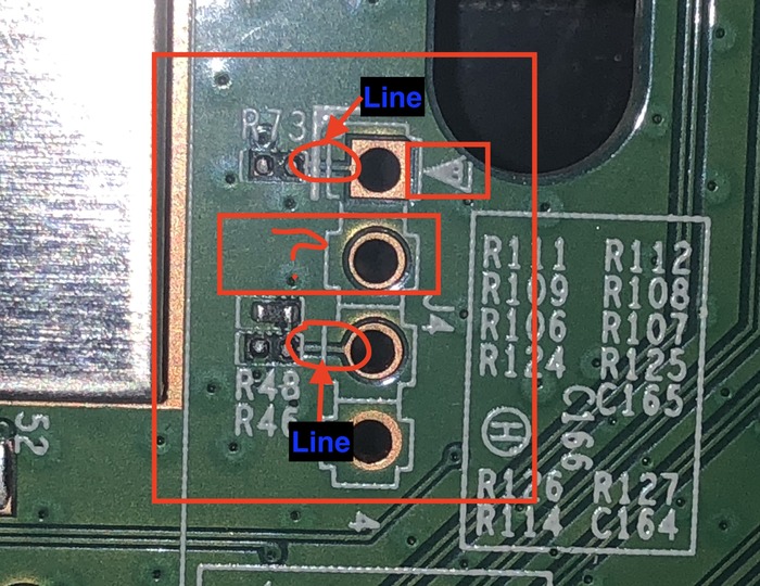
Firstly, to confirm the GRND pin, we set the multimeter to continuity mode and set the positive (red) probe on the port and the negative (black) probe somewhere on the device that is grounded (e.g. metal plate). The beep sound confirms that the bottom outer pin is indeed the GRND. Now for the rest of the pins, the Vcc pin reading should be a constant 3.3 Volts. RX should read 0 since it is expecting data input. TX should osclillate between 0 to 3.3 V since that is the data that the router is sending. In this case, the RX pin gave a constant voltage reading of 3.3 V and is the pin not connected to the line. This is an attempt to disable RX by the manufacturer. To solve this issue, we can do something hacky like using an electrical conductor (e.g. paper-clip) to connect the pin to a line, however, I decided to read data from TX first.
Connecting to UART
To connect to the UART Debug interface, I used the attify badge device. This device speaks a wide variety of communication protocols and standards including UART, SPI, I2C, 1-Wire and JTAG. It also supports 3.3 and 5 V; allowing us to interact with a wide variety of embedded devices. Note that the RX pin on the attify badge should be connected to the TX pin of the router and vice-versa. We can then use PuTTY as a serial console and interface with the attify badge to read the data the router is sending. For our purposes, we only need to connect to read and GRND. See below image for the physical setup.
![]()
Cool. Now we can configure PuTTY to connect to the serial console. We need two things (1) the COM port at which our attify badge device is connected and (2) the baudrate; essentially the rate at which the router is transferring data. To identify the COM port, you can use the windows device manager. Make sure to select ‘show hidden files’ from the ‘view’ menu. In my case, the COM port number is 3. For the baudrate, we can use a python script to detect it automatically. The script is a bit slow so a few manual tries using the most common baudrates is not a bad idea. For this device, the baudrate is 57600. Now we are ready to configure PuTTY and hopefully read data.
Boot Logs!
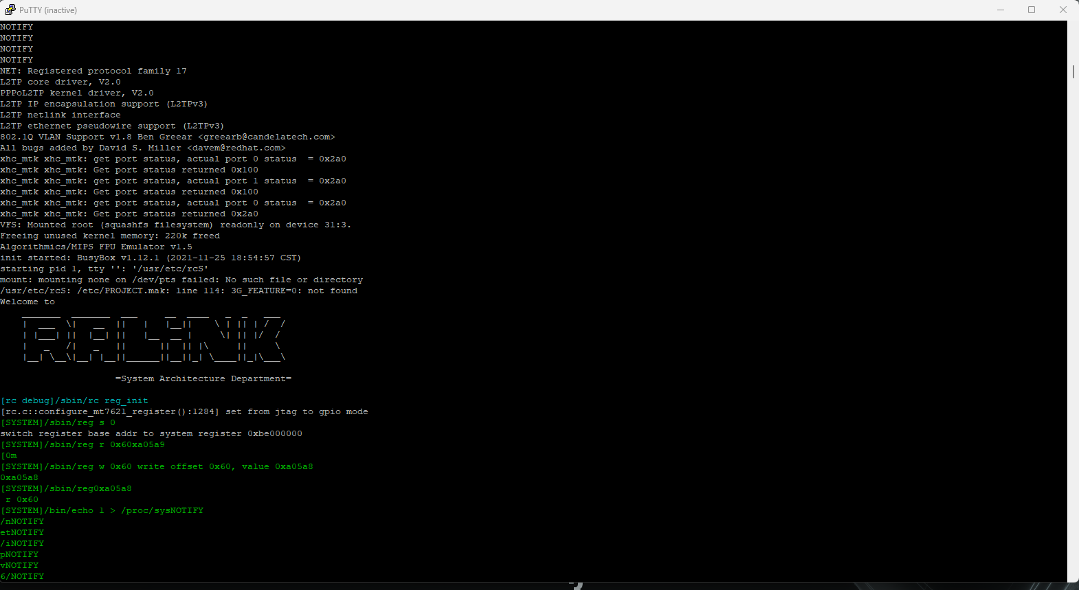
To configure PuTTY, select ‘serial’ for the connection type - set the COM port assigned to the attify badge - input the identified baudrate. Make sure that your jumper wires are correctly and securely connected to the UART ports of the router. In my case, just inserting some header pins without soldering works perfectly fine. With everything setup, you should see data being written to the PuTTY console. Nice! If you are receiving non-readable data, its most likely a baudrate issue.
Getting a shell
The bootlogs are a treasure trove of information. It is best that PuTTY is configured to log the session in a file to make the analysis part easier. To ensure that all boot log information is retrieved, reboot the device while connected to the UART interface.
At this point, I manually sifted through the boot logs and made notes on interesting information including:
Filesystem info
VFS: Mounted root (squashfs filesystem) readonly on device 31:3.
Freeing unused kernel memory: 220k freed
Algorithmics/MIPS FPU Emulator v1.5

init started: BusyBox v1.12.1 (2021-11-25 18:54:57 CST)
Startup script
starting pid 1, tty '': '/usr/etc/rcS'
mount: mounting none on /dev/pts failed: No such file or directory
/usr/etc/rcS: /etc/PROJECT.mak: line 114: 3G_FEATURE=0: not found
Welcome to
    _______  _______  ___     __  ____   _  _   ___
    |  ___  \|   __  ||   |   |__||    \ | || | /  /
    | |___| ||  |__| ||   |__  __ |     \| || |/  /
    |   _   /|   _   ||      ||  || |\     ||     \
    |__| \__\|__| |__||______||__||_| \____||_|\___\

                =System Architecture Department=
Running processes
...
 1493 root      1220 S    telnetenabled 192.168.1.1 3894EDFCF3F8 admin 83BtOyeG
 1523 root      2500 S    /usr/sbin/dbus-daemon --config-file=/etc/dbus-1/syste
 1524 root      1548 S    /bin/sh /etc/ad_arpd
 1538 root      1544 S    sleep 30
 1561 root      1664 S    /usr/sbin/miniupnpd -i eth3 -a 192.168.1.1 -p 56688 -
...
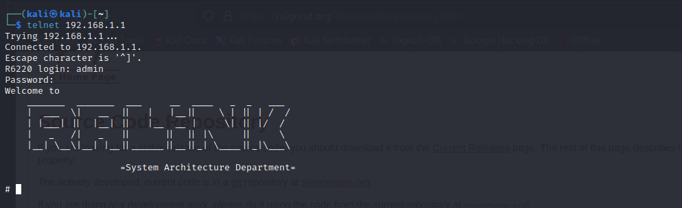
Looking closely at the process list, it is evident that the router is running a telnet daemon. This is looks like the shortest path to our shell. Note that the initial Nmap scan did not detect the telnet service. Quick googling around and I stumbled on this source. It seems that Netgear routers have a built-in administrative telnet backdoor that can be enabled using the router’s web interface. I enabled the telnet service using the following URL: http://192.168.1.1/setup.cgi?todo=debug. To log in, I used the credentials of the admin user of the router’s web interface.
What now?
With a shell on the device, we can setup a remote debugging session with gdb-server to reverse engineer service binaries or other binaries accessible from the web interface (.cgi). We can also exfiltrate these binaries to our local box to sync our static and dynamic analysis. More on this in part 2!
Equipment List
The following list includes all physical equipment used during this engagement.